time:2026-09-24 11:13:48Views:
Select a pump VFD by motor full-load current first, then by hydraulics. Take the motor nameplate FLA, add a 5-10% margin, and choose a normal-duty (variable-torque) VFD rated for 110-120% overload for 60 s. Then confirm the control features the application actually needs - built-in PID, sleep/wake, dry-run input, multi-pump staging - and set the minimum frequency at 20-25 Hz so the pump never runs below its minimum continuous flow. Mingcheng supplies these drives from stock for export markets.
A pump variable frequency drive (also called a frequency inverter or AC drive) varies the speed of the motor driving a centrifugal pump instead of running it at fixed mains speed. Because a centrifugal pump is a variable-torque load, it follows the affinity laws: flow is proportional to speed, head is proportional to the square of speed, and shaft power is proportional to the cube of speed.
| Relation | Formula | Meaning |
|---|---|---|
| Flow | Q2 / Q1 = N2 / N1 | Flow falls linearly with speed |
| Head | H2 / H1 = (N2 / N1)2 | Pressure falls with the square of speed |
| Shaft power | P2 / P1 = (N2 / N1)3 | Power falls with the cube of speed |
A pump moved from 50 Hz to 45 Hz (90% speed) needs roughly 73% of the shaft power; at 75% speed the figure drops to about 42%. That is why variable-speed control on a throttled or bypass-controlled pump typically returns 20-40% energy savings - a throttling valve dissipates head, while the VFD removes the head from the pump curve entirely. Two caveats matter: a system dominated by static head (deep well, high lift) saves much less at low speed, and a pump running far from its best efficiency point (BEP) stays inefficient no matter how good the drive is. Always calculate savings against the real pump curve and system curve intersection, not the idealised cube curve.
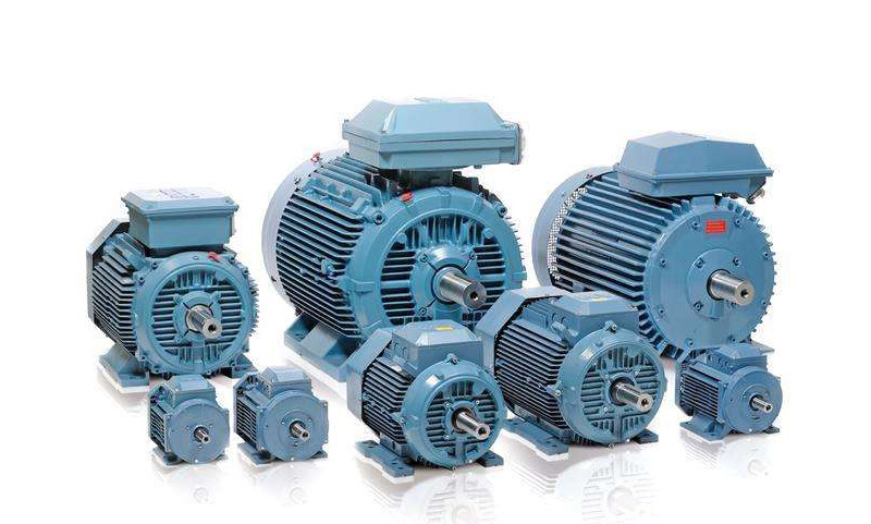
Work through these nine steps in order. Each one removes a specific cause of nuisance trips and short drive life.
Collect the hydraulic envelope. Design flow (m3/h or gpm), total dynamic head, minimum and maximum static head, NPSH available, and the suction and discharge piping layout.
Read the motor nameplate. Rated kW/HP, voltage, frequency, full-load amps (FLA), poles, service factor, insulation class and IP rating. Enter the real FLA into the drive - a wrong FLA is the most common cause of false overload trips.
Confirm the pump curve. Best efficiency point (BEP), minimum continuous stable flow, required NPSH and runout flow for the actual impeller trim.
Size by current, not by kW. Continuous output current must meet or exceed motor FLA plus 5-10% for harmonics and switching losses. Example: a 15 kW motor at 29 A needs a drive rated for at least about 31 A.
Match the duty class. Centrifugal pumps are variable-torque: specify normal duty (110-120% overload for 60 s). For positive-displacement, grinder and chopper pumps - constant torque with high starting torque - step up to a heavy-duty drive at 150% overload for 60 s.
Apply environmental derating. Above 40 C, derate roughly 1.5% of current per degree; above 1,000 m altitude, derate about 1% per 100 m. In well houses, wash-down areas and coastal plants, prefer IP55 enclosures and coated boards.
Select the control mode and V/Hz curve. Centrifugal pumps normally run scalar control with a squared (quadratic) V/Hz curve to match the load and cut losses at low speed. Use sensorless vector if the same drive also serves constant-torque machinery.
Decide the pump control architecture. One drive / one pump with a bypass contactor for critical service; one drive / multiple pumps (sequential or synchronous); or one drive per pump.
Fix the protection and interface set. Minimum frequency 20-25 Hz to stay out of recirculation, dry-run input, sleep/wake, pipe-fill ramp, and Modbus RTU/TCP or BACnet/IP for SCADA.
If three or more of these are paid firmware options rather than standard, the drive is probably not pump-dedicated and total cost of ownership will rise during commissioning.
| Feature | Why a pump application needs it |
|---|---|
| Built-in PID | Closed-loop pressure or flow control without an external controller |
| Sleep / wake | Stops the pump at low demand; prevents water heating and seal damage |
| Multi-pump staging | Adds and removes fixed-speed pumps as demand moves |
| Pipe-fill function | Closed-loop ramp that prevents surge in an empty pipeline |
| Dry-run / no-flow detection | Protects seal and impeller when suction is lost |
| Minimum frequency limit | Keeps the pump above minimum continuous flow |
| Energy logging | Reports kWh saved for tariff and audit reporting |
| Built-in EMC filter / reactor | EN 61800-3 compliance and IEEE 519 harmonic control |
| Coated circuit boards | Survival in humid, well-house and outdoor enclosures |
The series below are stocked by Mingcheng as an authorized distributor and cover the usual pumping duties. See the full drive product range for other power classes.
| Series | Power span | Pump-relevant character |
|---|---|---|
| ABB ACS310 | 0.37-22 kW | Micro drive dedicated to pump and fan variable-torque duty, built-in multi-pump and pipe-fill logic |
| ABB ACS510 | 1.1-160 kW | Classic pump/fan series, cycling soft-start, built-in RFI filter and swing-choke reactor |
| ABB ACS580 | 0.75-500 kW | ACS550 successor; standard PID, pump functions, energy optimizer, coated boards |
| ABB ACQ580 | 0.75-500 kW | Water and wastewater variant - the most complete pump programme |
| ABB ACS880 | 0.55-3200 kW | Industrial DTC drive for large pumps or mixed plant duty |
| Schneider Altivar | 0.18 kW - MV | ATV212/ATV600 for building and process pumping; Altivar 1200 for medium-voltage pump stations |
| INVT GD series | 0.4 kW - HV | Cost-effective low-voltage pump drives; GD5000 for 6/10 kV pump stations |
Parameter numbers below are indicative and must be verified against the parameter list shipped with the drive - ABB reorganised the PID group between ACS580 firmware generations, and the ACS510/ACS355 use Group 40 with three-digit numbering.
| Function | Indicative parameter | Starting value |
|---|---|---|
| PID gain / integration | 40.02 / 40.03 | Gain 8-12, integration 15-20 s |
| PID feedback / setpoint source | 40.08 / 40.09 | Pressure transmitter on AI1/AI2, 4-20 mA scaled to engineering units |
| Sleep mode | 40.21 | Internal |
| Sleep level | 40.22 | 32-35 Hz |
| Sleep delay | 40.23 | 5-10 s |
| Wake-up deviation | 40.24 | 10-15% of the pressure setpoint |
| External fault (dry run) | 31.01 / 31.02 | Source DI3 or DI4, type = Fault |
| Min / max frequency | 30.11 / 30.12 | Minimum 20-25 Hz |
| Accel / decel ramp | 23.11 / 23.12 | 15-30 s, longer for tall risers |
Expansion tank note: for VFD-controlled constant-pressure systems a small vessel of 8-24 L is sufficient and responds faster than an oversized tank. Pre-charge the air side to 60-70% of the target pressure (3.0 bar target gives 1.8-2.1 bar pre-charge) and check it every six months. A flat or ruptured membrane makes the drive cycle every few seconds, which wears the power stage and the motor windings.
Most pump VFD alarms are mechanical or hydraulic problems reported electrically. Work outward from the drive, and check the fault log before replacing anything.
| Symptom | Likely cause | Corrective action |
|---|---|---|
| Overcurrent (OC) trip on start | Accel ramp too short, water hammer, debris on the impeller, seized bearings | Lengthen accel to 15 s or more; megger the motor; inspect and rotate the impeller |
| Overvoltage (OV) trip on stop | Regenerated energy on a long decel or a tall riser exceeds DC-bus capacity | Lengthen the decel ramp, enable overvoltage stall control, add a braking resistor |
| Pressure oscillates / pump hunts | PID gain too high or integration too low; transducer in turbulent flow; feedback not scaled | Cut gain about 20%, lengthen integration about 50%, move the transmitter to laminar flow |
| Pump never sleeps, or wakes with no demand | Sleep level too low for the installed pump; wake-up deviation too small; tank pre-charge lost | Raise sleep level by 0.5-1.0 Hz; raise wake-up deviation to 15-20%; re-charge or replace the tank |
| Cavitation noise, vibration, seal failure | Operating below minimum continuous flow; NPSH margin exhausted | Raise minimum frequency to 20-25 Hz, add a minimum-flow bypass, recheck NPSHa against NPSHr |
| Motor overheating at low speed | TEFC shaft fan loses cooling below about 30 Hz; linear V/Hz curve over-fluxes | Use the squared V/Hz curve, keep minimum frequency at 10-15 Hz, or fit forced ventilation |
| Dry-run fault (e.g. F0009 / external event 1) | Suction lost - level dropped, strainer blocked, valve closed | Verify the float or pressure switch on DI3/DI4, clean the strainer, check the suction valve |
| Recurring OC on a grinder or chopper pump | Constant-torque load on a variable-torque drive rating | Re-size to a heavy-duty drive at 150% overload for 60 s |
| Erratic faults, noise on signal wires | Poor grounding, common-mode noise, signal cable run with power cable | Shield grounded at one end only, separate conduits, motor grounded to the drive |
More drive questions are answered in our FAQ section.
Read the motor nameplate FLA and the pump curve first, then choose a normal-duty variable-torque drive whose continuous output current exceeds the motor FLA by 5-10%. Confirm built-in PID, sleep/wake, dry-run input and multi-pump staging, set the minimum frequency at 20-25 Hz, and use accel and decel ramps of 15-30 s to avoid water hammer.
Size by current, not kW. At 29 A nameplate on 380-400 V, select a drive with at least about 31 A continuous output (29 A x 1.05-1.10). The kW label on the drive is only a cross-check - the same 15 kW motor can draw noticeably different current depending on pole count and efficiency class. Send us the nameplate and we will confirm the size.
Yes for simple duties - multi-speed presets or manual speed control work if demand is constant, and level control can use a float switch. Closed-loop constant pressure, however, needs a transmitter on the drive's analog input plus a properly scaled 4-20 mA signal; without correct scaling the PID regulates to the wrong pressure.
Usually 20-25 Hz. Below minimum continuous stable flow the pump recirculates, which raises vibration, seal temperature and impeller erosion. Separately, a standard TEFC motor without forced ventilation should not run below 10-15 Hz for long periods, so the pump limit normally governs.
Lengthen the deceleration ramp to 20-30 s, enable overvoltage stall control so the drive extends the ramp instead of tripping, and for very tall risers add a soft-stop extension at low frequency. Verify the check valve closes cleanly - discharge pressure rise should stay under roughly 10 psi.
For new constant-pressure and booster stations, the ACQ580 is the pump-dedicated choice with the most complete pump programme. The ACS580 is the general-purpose alternative that also covers conveyors and mixers, and the ACS510 remains a proven, economical pump/fan series for retrofit and standard duties. We supply all three, and the ACS880 for large pump stations.
## 补充 Schema

Keep up on our always evolving product features and technology. Enter your e-mail and subscribe to our newsletter.